This guide briefly describes various oscillator circuits.
LC Oscillators[]
Inductor-Capacitor based oscillators.
Colpitts Oscillator[]

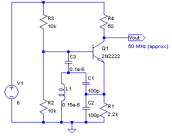

A simplified version of the formula is this:

Hartley Oscillator[]
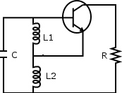
Pros:
- Frequency varied using a variable capacitor
- Output amplitude remains constant over the frequency range
- Feedback ratio of tapped inductor remains
Cons:
- Harmonic-rich content
- Not suitable for a pure sine wave
Clapp Oscillator[]


Armstrong Oscillator[]
 based on the Regenerative Receiver circuit
Blocking Oscillator[]
Wien bridge[]
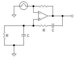

Phase Shift Oscillator[]
This uses any opamp and shifts the phase of the feedback. It is very simple to get working.
- Full equations

Oscillation Criteria:

- Simplified equations
To use this equations and and


Square wave (Digital Logic)[]
in digital speak: astable multivibrator
Multivibrator[]

The circuit has two states:
State 1':
- Q1 switched on
- Collector of Q1 at 0V
- C1 test charging through R2 (and Q1)
- Voltage at base of Q2 is the voltage across C1. This is initially low, but rising as C1 charges.
- Q2 switched off (assuming base voltage < 0.6V)
- C2 discharging through R3 and R4
- Output voltage high (although a little lower than the supply voltage because of the C2 discharge current through R4)
- This state is self-maintaining until the voltage at base of Q2 reaches 0.6V, at which point Q2 switches on, and the circuit goes into the following state.
State 2
- Q2 switched on
- Collector of Q2 (output voltage) goes from +V to 0V
- This step change on C2 causes a negative going pulse on the base of Q1, which rapidly switches it off.
- Q1 switched off, its collector rises to about +V.
- C1 discharging through R1 and R2
- C2 charging through R3 from -V through 0v to +0.6v (this might be considered a discharge rather than a charge)
- Voltage at base of Q1 is the voltage across C2. This is initially low, but rising as C2 charges.
- This state is self-maintaining until the voltage at base of Q1 reaches 0.6V, at which point Q1 switches on, and the circuit flips back into state 1.
Initial power-up
When the circuit is first powered up, neither transistor will be switched on. However, this means that at this stage they will both have high base voltages and therefore a tendency to switch on, and inevitable slight asymmetries will mean that one of the transistors is first to switch on. This will quickly put the circuit into one of the above states, and oscillation will ensue.
Period of oscillation
Very roughly, the duration of state 1 (high output) will be related to the time constant R2.C1 as it depends on the charging of C1, and the duration of state 2 (low output) will be related to the time constant R3.C2 as it depends on the charging of C2 — and these time constants need not be the same, so a custom duty cycle can be achieved.
However, the duration of each state also depends on the initial state of charge of the capacitor in question, and this in turn will depend on the amount of discharge during the previous state, which will also depend on the resistors used during discharge (R1 and R4) and also on the duration of the previous state, etc. The result is that when first powered up, the period will be quite long as the capacitors are initially fully discharged, but the period will quickly shorten and stabilize.
The period will also depend on any current drawn from the output.
Because of all these inaccuracies, more sophisticated timer ICs are commonly used in practice, as described above.
Ring Oscillator inverter[]
![]() An odd number of inverters are required. Using a minimal number of stages within the oscillator allows for maximum frequencies to be achieved, however this will be sensitive to voltage variations. By using a larger number of stages, the noise, due to voltage variation is minimised. The frequency is not exact due to variations in transition time. This is compensated for by controlling the current passing through the transistors. This also allows you to make it a Voltage controlled oscillator (VCO).
An odd number of inverters are required. Using a minimal number of stages within the oscillator allows for maximum frequencies to be achieved, however this will be sensitive to voltage variations. By using a larger number of stages, the noise, due to voltage variation is minimised. The frequency is not exact due to variations in transition time. This is compensated for by controlling the current passing through the transistors. This also allows you to make it a Voltage controlled oscillator (VCO).
CMOS Crystal Oscillator[]
Schmitt Trigger inverter Oscillator[]

This can be built from the ic of ttl serie 7414, 74ls14... or the form the 4000 cmos series (e.g.:4093).
This can be used in the place of other Oscillators.
T = 1.7*RC
Stable RC Oscillator[]
555 timer[]
This is probably the most common oscillator for amateur electronics hobbyists, because it is a common IC, and well documented
Other oscillators[]
- broad band amplifiers
- buffer amplifiers
- crystal oscillators
- emitter degeneration
- hartley oscillator
- negative feedback
- voltage controlled oscillators
- oscillator drift
- Armstrong oscillator
- Astable multivibrator
- Blocking Oscillator
- Clapp oscillator
- Colpitts oscillator
- Crystal oscillator
- Electronic oscillator
- Hartley oscillator
- Relaxation oscillator
- RLC circuit
- Vackar oscillator
- Royer oscillator
- OCXO (short for Oven Controlled X-tal (Crystal) Oscillator) is a technique used for avoiding temperature changes that affect the resonance frequency of a piezoelectric crystal.
How to make a simple oscillator, making your own inductor and capacitor[]
In electronics, an oscillator is a circuit that generates a signal at a certain frequency. You can make a simple oscillator with an inductor (a coil) and a capacitor (two parallel plates). The circuit will alternately store energy in the capacitors (electrical energy) and in the inductor (magnetic energy). The electrons coming off one plate will pass through the inductor. As the charge on the plates becomes constant, the current dies. The drop in current creates an electromotive force in the inductor that propels electrons to continue in the same direction, thus charging the other capacitor plate. You'll Need:
- 2 rolls of Saran Wrap
- Roll of aluminum foil
- 2 bare wires
- Thin insulated copper wire
- Cardboard tube
- Battery
Step 1: Create a capacitor as follows, if you don't have one handy. Unroll two rolls of Saran Wrap a few feet. Place a few feet square of aluminum foil on each unrolled area so that the Saran Wrap extends out farther (covers more area) than the aluminum sheets. This extra extension will provide electrical insulation between the "plates" when the two sheets of Saran Wrap and aluminum are rolled up together again. Now cut the Saran Wrap at the edge of one of the Saran Wrap rolls and place the newly cut-off Saran Wrap-aluminum sandwich squarely onto the other Saran Wrap-aluminum sandwich. This makes a Saran-Wrap-foil-Saran-Wrap-foil sandwich. The bottom Saran Wrap layer is still connected to its roll of Saran Wrap. Insert two bare wires into the sandwich at different layers to contact the two aluminum sheets. Then roll up the whole thing into the Saran Wrap roll that is still attached to the bottom Saran Wrap layer. The Saran Wrap layer between the two foil layers keeps them insulated from each other like an air in a conventional capacitor.
Step 2: Tape the capacitor wires to opposite ends of a battery with electrical tape. This will charge up the capacitor. Let it charge for an hour, just like you'd charge a battery. <a href="http://www.ehow.com/how_5652134_make-simple-oscillator.html" class="external free" rel="nofollow">http://www.ehow.com/how_5652134_make-simple-oscillator.html</a>